A black a white one red one blue and one yellow. Tridonc t5 twin ballast wiring change tridonic diagram saab trionic corridorfunction pc pro lp 14 80 w fluoescent advice required hf 1620 cub pca xitec ll product manual 2 70 t8 sl top 54 2018 web kat en part1 by philips emergency electronic 3 4x18 fl ballasts dimming tc single lc 42 700 900 1050 ma flexc sr adv power packs.
Http Www Mercuryconvention Org Portals 11 Documents Meetings Cop4 Submissions Clasp Annexab Marketstudy Pdf
Refer to pages for ballast dimensions and wiring diagrams.

Ge ballast wiring diagram for sings. Count on GE to answer your sign lamp and ballast questions at 1-888-GEBALLAST. 1-6 Lamp T12HO Survivor Sign Ballast Part Description Lamp Type of lamps Min Starting Temp. Line Volts Dimming Levels System Watts Nom.
Convert your existing linear fluorescent fixture to LED without needing a comprehensive reinstall. Lamp length Input Volts Input Watts Input Current Amps Open Circuit Volts Dim. It shows the elements of the circuit as simplified shapes as well as the power and signal links between the gadgets.
4 Lamp T8 Ballast Wiring Diagram 4 lamp t8 ballast wiring diagram 4 lamp t8 emergency ballast wiring diagram Every electric structure is made up of various different pieces. Also available in Single Ended Ballast Bypass Configurations. Cut back additional wiring on opposite side of ballast as the LED Tube lamp only requires power at one end.
Type Wiring Diagram Fig 72103 GESB-0412-12-IP F24T12HO 2. Fl Ballasts Electronic Dimming Pca Tc Eco Y Ii 11 â 57 Tridonic. Each part ought to be set and linked to different parts in specific way.
From the ballast leaving a sucient amount of wire to connect back to the 110 VAC power source. Strip the load and neutral wires. It reveals the components of the circuit as streamlined forms and the power and also signal links in between the gadgets.
Assortment of sign ballast wiring diagram. See product specification sheets for more information Existing fixture is wired to bypass the ballast. Adjoining cord courses could be revealed about where certain receptacles or fixtures must be on an usual circuit.
Assortment of ge t12 ballast wiring diagram. If not the structure will not work as it ought to be. The easy-to-understand model numbering system helps you choose and install the right model.
Line Current System Ballast Factor. 2 lamp t12 ballast wiring diagram ge 2 ft and 4 t5 120 lamp ballast wiring diagram 6 bjzhjy net rh bjzhjy net T12 Magnetic Ballast Wiring Diagram T12 Ballast Wiring Diagram. Electronic sign ballasts have many advantages over magnetic ballasts in addition to their energy savings.
Remove the ballast from the tube lamp housing and save the original wiring that connected to the 110VAC. The black connects to a red power wire in the ceiling the white to the whtie neutral and the single red blue and yellow wires all connected to matching wires on the fixture to the left. A wiring diagram is a streamlined conventional pictorial representation of an electric circuit.
So I bought 2 GE proline t12 ballast for 2 f96t12 this one had a black and white wire When in doubt read the wiring diagram on the ballastWiring Diagrams GE Survivor T12HO Fluorescent All-Weather Sign Ballasts Figure 4 Figure 5 Figure 6 Figure 7 Figure 8 Figure 9. When removing the ballast use diagram A1 or A2. These ballast wire exactly like the original but you must cycle power after both.
A wiring diagram is a streamlined standard pictorial representation of an electric circuit. Sign ballast wiring diagram Building electrical wiring layouts show the approximate places as well as affiliations of receptacles lighting and long-term electric solutions in a building. It shows the components of the circuit as streamlined forms and also the power and signal links in between the tools.
Before restoring power use wire nuts to cover exposed ends of any wires. Smart Wire and Parallel Wire. The old ballast had two blue and two red wires on the right and on the left side.
A wiring diagram is a streamlined standard photographic representation of an electric circuit. Reduces energy use vs type A Eliminates the need to check ballast compatibility. Replacing a ballast of the same type 3 lamp with 3 lamp parallel with parallel Replace 3 Lamp Instant Start Ballast with 4 Lamp Instant Start Wiring Diagram.
Remove power from the fixture before replacing lamps or modifying ballast. The ICN-2SSC electronic ballast from Philips Advance is a new lamp One or two F96T12HO fluorescent lamps can be operated on this ballast with these. And if you prefer PDF documents on the subject this one from GE is pretty good.
GE MVP T12 ballasts have the same wiring and mounting requirements as. Apply the label located to the right included with luminaire after installation in any visible location on the fixture. In 2014 the Department of Energy outlawed magnetic sign ballasts due to their inefficiency.
A wiring diagram is a simplified standard photographic representation of an electrical circuit. Collection of ge t12 ballast wiring diagram. The new ballast shouldve come with a wiring diagram.
To make upgrading to an electronic ballast as easy as possible Keystone offers two solutions. Assortment of fluorescent ballast wiring diagram. It reveals the parts of the circuit as streamlined forms as well as the power and also signal links in between the devices.
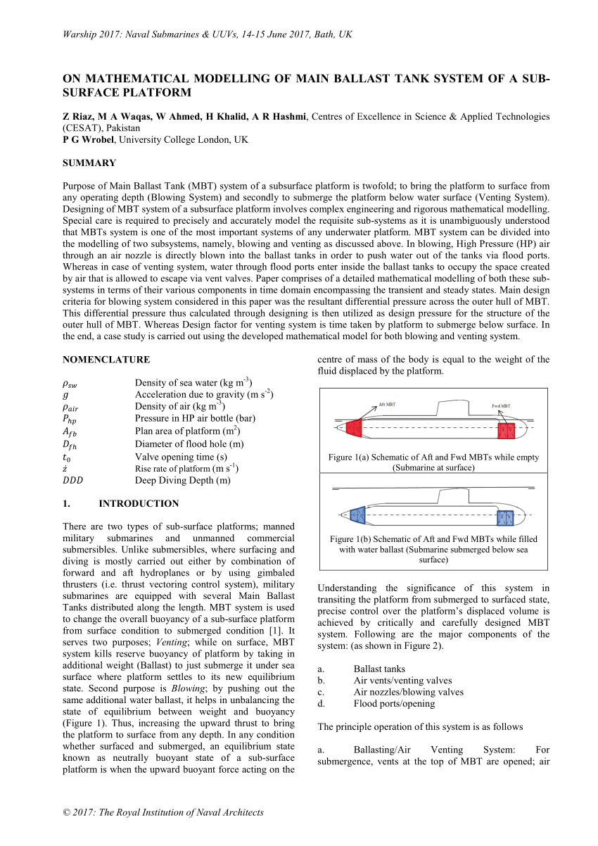 Pdf On Mathematical Modelling Of Main Ballast Tank System Of A Sub Surface Platform
 Pdf Systems Of Environmental Innovation Sectoral And Technological Perspectives On Ballast Water Treatment Systems
 Ge T12 Ballast Wiring Diagram 1967 Ford F100 Wiring Diagram For Wiring Diagram Schematics
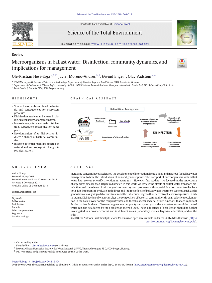 Pdf Microorganisms In Ballast Water Disinfection Community Dynamics And Implications For Management
 How To Direct Wire A Fixture For Single Ended Led Lamps Energy Focus
No comments:
Post a Comment